Designing an API as Hub Architecture to Connect Two Independent Healthcare Systems
Connecting two independent healthcare systems is always more complicated than the surface requirements suggest. I recently had to design a near-real-time integration between two products that historically lived in complete isolation. Each platform had its own backend, database, data model, and operational assumptions. Now they needed to exchange information bi-directionally—without becoming tightly coupled and without compromising reliability, performance, or compliance.
Both systems handled part of the medication lifecycle within hospitals. One tracked where medications physically were. The other tracked when medications were administered to patients. These two data sets are complementary, but the products were built years apart, by different teams, and were never designed to communicate.
The challenge:
Enable these systems to share data reliably, securely, and in near real time.
After exploring multiple approaches, I decided to build an API as Hub architecture—a centralized integration layer that sits between the products, handles entitlements, normalizes data, caches frequently accessed content, logs every interaction for audit, and routes requests safely and efficiently.
This article explains how I designed that architecture, including security considerations and PHI protocols.
1. The Problem: Two Products, Zero Connectivity
The two systems were built independently:
- System A: Knows where medication containers or vials physically are across hospital units.
- System B: Knows when a medication was administered to a patient.
The new feature requirements required bi-directional data sharing, for example:
- System B wanted to understand where a medication originated.
- System A wanted to understand which doses were administered and when.
Both systems exposed APIs, but directly integrating them would create:
- Hidden dependencies
- Difficult-to-debug failures
- No central auditing
- No entitlement enforcement
- No standard schema
- A pattern that would not scale when additional products were eventually introduced
Given the constraints, the cleanest approach was a centralized integration hub.
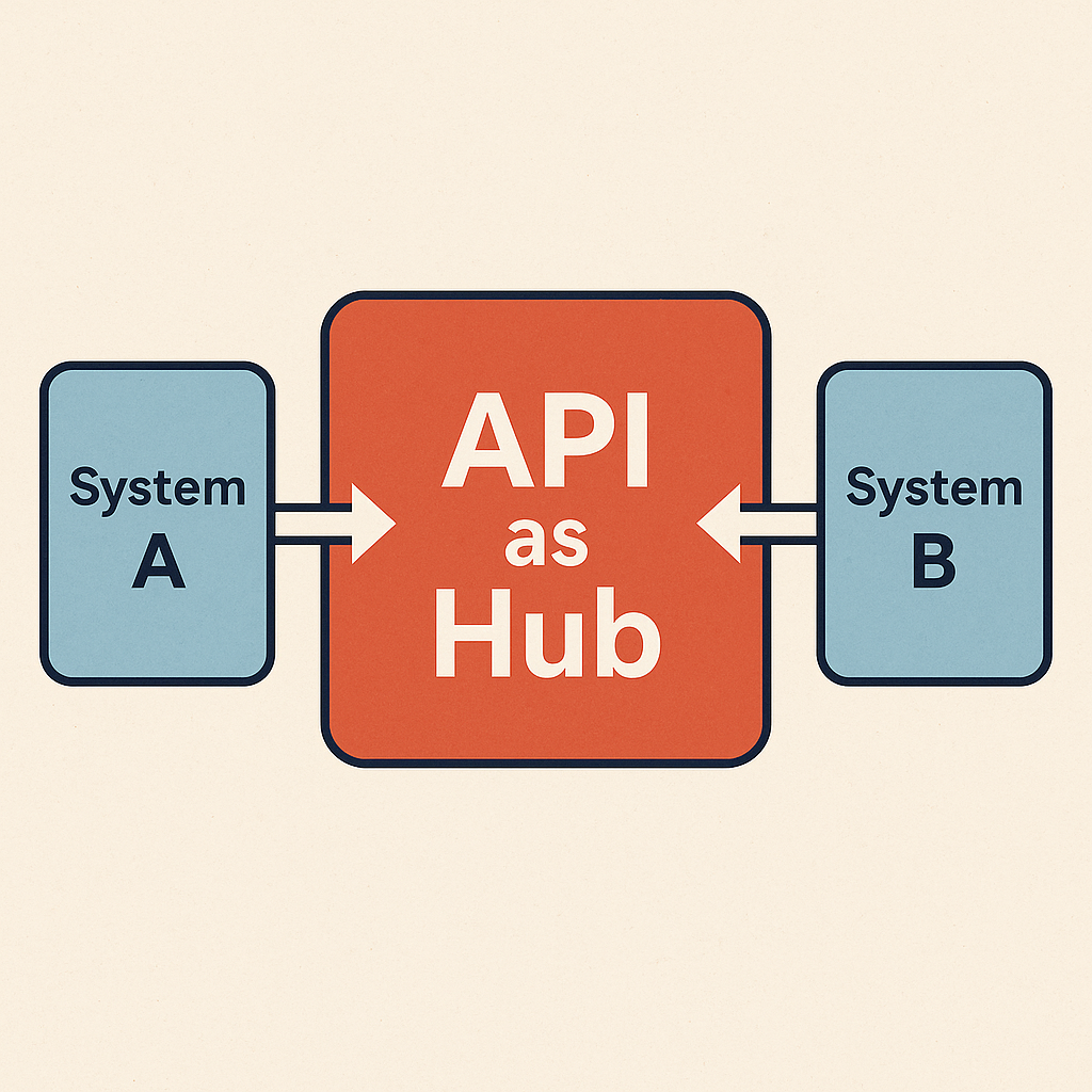
2. Why an API as Hub?
Instead of having System A and System B call each other, I designed a central API layer that performs:
- Authentication and machine-to-machine authorization
- Customer entitlement and product-access checks
- Request routing
- Response normalization
- PHI-aware processing
- Caching
- Observability and full audit trails
- Retry and resiliency policies
- Async job orchestration for heavy workloads
This pattern ensures clean boundaries, scalability, and a single place to enforce compliance.
Here’s the high-level structure:
     +------------------+
     |     System A     |
     |  (Inventory API) |
     +--------+---------+
              |
              |  API call
              v
        +-------------+
        |  API as Hub |
        +-------------+
              ^
              |
              |  API call
     +--------+---------+
     |     System B     |
     |  (Admin API)     |
     +------------------+
3. Request Lifecycle Inside the API Hub
When System A requests administration data stored in System B, the Hub performs the following steps:
Step 1 — Auth
The Hub validates machine-to-machine credentials and resolves the request to a tenant.
Step 2 — Entitlement Check
Not all customers own both systems.
The Hub checks:
- Does this customer have access to System B’s data?
If not, the Hub returns a 403—before calling downstream and before touching PHI.
Step 3 — Cache Layer
The Hub checks Redis for a cached response:
cache.get("customer:123:systemB:administrations")
If present and fresh, the Hub returns it immediately.
Step 4 — Downstream Routing
If a cache miss, the Hub calls System B’s API, applying retry and backoff policies.
Step 5 — Data Normalization
System B may return a schema incompatible with System A.
The Hub converts it into a canonical schema that all products can consume consistently.
Step 6 — Auditing
Every request and response is logged without storing PHI.
Step 7 — Response
The Hub returns a PHI-minimized, schema-normalized payload to System A.
4. Handling Heavy Workloads: Asynchronous Aggregation
Some requests can’t be served synchronously. Example:
“How many administrations of Drug X occurred today across all units?”
System B stores individual events. Aggregating them may involve thousands of records.
For that, I added an async pipeline using a queue:
System A → API Hub → SQS → Aggregation Worker → Results DB → API Hub → System A
ASCII diagram:
+------------+       +-------------+       +----------------+
|  System A  |  -->  |   API Hub   |  -->  |      SQS       |
+------------+       +-------------+       +--------+-------+
                                                   |
                                                   v
                                          +------------------+
                                          | Aggregation Job  |
                                          |     Worker       |
                                          +--------+---------+
                                                   |
                                                   v
                                           +---------------+
                                           |   Results DB  |
                                           +-------+-------+
                                                   |
                                                   v
                                        System A polls jobId
This keeps the Hub responsive and lets heavy work scale independently.
5. Security and PHI Handling
Because both systems operate in clinical environments, the integration layer must be secure by design. The Hub is not a pass-through router; it is a compliance boundary.
Below are the primary security controls I designed.
A. Transport + Storage Encryption
- All traffic uses TLS end-to-end.
- Databases, caches, and object stores are encrypted at rest (e.g., via KMS).
- Redis is deployed in a private network, with authentication and TLS.
The Hub never writes PHI to unencrypted storage.
B. Strong Authentication & Least Privilege
- Each system authenticates with service credentials (not user tokens).
- The Hub validates:
- System identity
- Customer identity
- Product access
- All secrets live in a secret manager, not code.
Downstream system access uses credentials scoped to minimal permissions.
C. Tenant Isolation
Every request is tenant-scoped.
Cache keys look like:
customer:{tenantId}:product:{system}:resource:{type}
Queue messages include tenant metadata.
No cross-tenant aggregation is allowed unless data is de-identified.
D. PHI-Aware Logging and Auditing
Logs contain:
- Request IDs
- Operation types
- Status codes
- Latency
- Tenant ID
They explicitly exclude:
- Patient identifiers
- Medication notes
- Clinical context
A separate audit log retains high-level access traces required for compliance.
E. Network and Perimeter Controls
The Hub is not exposed publicly.
- Private networking or mTLS
- IP allowlists for known services
- Network security groups restricting inbound traffic
This ensures only trusted internal systems can access the Hub.
F. Data Lifecycle Policies
Temporary PHI (e.g., during aggregation) is deleted as soon as processing completes.
Historical data is purged or archived according to retention policies.
6. PHI Flow & Redaction Diagram
To illustrate how PHI is handled, redacted, or blocked, here’s the PHI-focused flow:
                +---------------------+
                |     System A        |
                | (Inventory API)     |
                +----------+----------+
                           |
                           | 1. Request w/ potential PHI
                           v
                 +-------------------------+
                 |     API as Hub          |
                 |-------------------------|
                 |  A. Auth & Entitlement  |
                 |  B. Tenant Scoping      |
                 |  C. PHI Redaction       |
                 |  D. Logging (No PHI)    |
                 +--+----------+-----------+
                    |          |
           (Allowed) |          | (Redacted / Denied)
                    |          |
  2. Downstream Call|          | 2b. Error/403, Logged w/out PHI
                    v          |
           +-----------------------+
           |      System B         |
           | (Admin API w/ PHI)    |
           +-----------+-----------+
                       |
                       | 3. Response containing PHI
                       v
              +----------------------+
              |    API as Hub       |
              |----------------------|
              | E. Normalize Data    |
              | F. Remove PHI Fields |
              | G. Cache (Limited)   |
              | H. Audit (Metadata)  |
              +----------+-----------+
                         |
                         | 4. Clean, normalized payload
                         v
                +--------------------+
                |     System A       |
                |   (PHI-Minimized)  |
                +--------------------+
This makes it clear:
- PHI is only fetched when allowed
- PHI is redacted before storage or logging
- Only the minimal necessary data is returned
7. Reliability and No Single Points of Failure
Healthcare systems must remain available even when one product has issues. The Hub includes:
- Multiple horizontally scaled instances
- Load balancer and health checks
- Circuit breakers to avoid cascading failures
- Retries with backoff
- Dead-letter queues for failed jobs
- Distributed tracing for troubleshooting
If System B goes down, System A still receives a clean, predictable error or cached fallback.
8. Growing Beyond Two Systems
This architecture isn’t limited to A ↔ B. It supports adding more systems by plugging connectors into the Hub:
           +-----------+
           | System A  |
           +-----------+
                 \
                  \
           +-------v-------+
           |   API as Hub  |
           +-------+-------+
                  / \
                 /   \
         +-------v-+ +--v--------+
         | System B | | System C |
         +----------+ +----------+
New systems only need:
- A connector
- Schema mapping
- Entitlement configuration
- Routing rules
Not a full N×N mesh.
Final Thoughts
Designing an API as Hub architecture forced me to think beyond simply transferring data. I had to build a foundation for secure, tenant-aware, PHI-safe, scalable communication across multiple independent systems. The result is a flexible integration pattern that doesn’t compromise security, performance, or compliance—and sets a consistent foundation for future product expansion.
Building this layer proved that with the right abstraction, previously isolated products can operate as a unified ecosystem, while keeping each system independent and maintainable.